M247
Order Number: XX-B0A96-FF
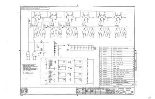
This document is a proprietary schematic diagram, copyrighted in 1970 by Digital Equipment Corporation, intended for test and maintenance purposes only.
Title: CONSOLE SWITCH FLIP FLOPS M247 (Part Number M247-0-1, Revision D).
Circuit Overview: The schematic details a digital logic circuit primarily composed of integrated circuits (ICs) configured as flip-flops and gates. Key components include:
- D-type Flip-Flops: DEC1074H74 (E1, E3, E5)
- NAND Gates: DEC1074H00 (E2, E6, E7, E8) and DEC1074H01 (E4)
The circuit shows multiple stages of flip-flops, often implemented using cross-coupled NAND gates, along with discrete D-type flip-flops, powered by +5V and +3V rails.
Component Specifications:
- Resistors: 1/4W, 5% (e.g., 2K, 1.2K, 270 ohm)
- Capacitors: .01uF, 100V, 20% (some also 39uF, 10V, 10% Tantalum; 120pF, 100V, 5%)
- Diodes: D662 and D664
- IC Pinout: Pin 7 = Ground, Pin 14 = +5V on each IC.
Parts List: A comprehensive bill of materials lists all required components by DEC part number, description, and quantity, including various ICs, resistors, capacitors, diodes, mechanical items (handle, eyelets), and the etched circuit board. It also references assembly, drilling hole layout, X-Y coordinate hole location, and module ECO history documentation.
Site structure and layout ©2025 Majenko Technologies