M246
Order Number: XX-7C65A-6B
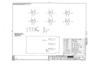
This document is an electronic schematic diagram for a "5D FLIP FLOPS" circuit, identified as Module M246-0-1, Revision A. It was copyrighted in 1970 by Digital Equipment Corporation and is designated for test and maintenance purposes, with the circuits being proprietary.
The schematic primarily features six D-type flip-flop logic gates, implemented using three DEC1074H74 Integrated Circuits. It also includes various passive components such as resistors (e.g., 220 Ohm, 330 Ohm) and capacitors (e.g., .01uF, 39uF) for power conditioning and regulation, with connections for +5V, +3V, and Ground.
General notes specify that resistors are 1/4W, 5% tolerance, and capacitors are typically .01uF, 100V, 20% tolerance, unless otherwise indicated. For the ICs, Pin 7 is designated as Ground and Pin 14 as +5V.
The document includes a comprehensive parts list detailing all components, including an etched circuit board, and mentions module ECO history and layout information. The schematic was drawn by S. Cooper on December 18, 1970.
Site structure and layout ©2025 Majenko Technologies