M172
Order Number: XX-142E9-81
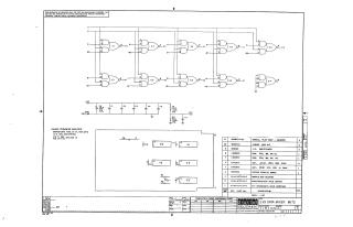
This document is a proprietary schematic diagram for a "2X9 DATA MIXER M172" printed circuit board, created by Digital Equipment Corporation and copyrighted in 1970. It is intended for test and maintenance purposes.
The schematic details:
- Digital Logic Circuitry: Primarily uses DEC1074H50 integrated circuits (ICs) configured as NAND gates to implement the data mixing function, showing inputs (C1, D1, E2, B1, D2) and various outputs (e.g., P2).
- Power Supply: Connections for +5V and +3V, along with ground, and associated filtering components including various capacitors (e.g., 0.39uF, 0.01uF) and resistors (220 Ohm, 330 Ohm).
- General Notes: Specifies that capacitors are typically 0.01uF, 100V, 20%, and standard IC power connections (Pin 7 to GND, Pin 14 to +5V).
- Parts List: A comprehensive list of components required for the M172-0-1 assembly, including ICs, resistors, capacitors, the etched circuit board, eylets, and a handle, along with their quantities.
- Administrative Details: The drawing number is M172-0-1, Revision A, and it was drawn by S. Cooper on December 16, 1970. An empty "Transistor & Diode Conversion Chart" section is also present.
Site structure and layout ©2025 Majenko Technologies