M165
Order Number: XX-464B7-52
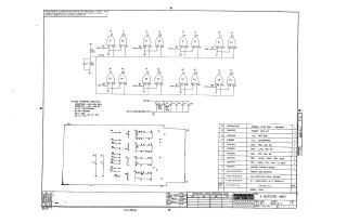
This document is a schematic diagram titled "8 BUFFERS MI65" (part number M165-0-1, Revision E), created by Digital Equipment Corporation in late 1970.
Key points:
- Purpose: It is furnished solely for test and maintenance purposes and contains proprietary circuits.
- Circuit Design: The schematic illustrates eight individual buffer circuits. Each buffer primarily utilizes pairs of integrated circuits (ICs), specifically DEC1074H00 (E1, E3) and DEC3001 (E2, E4) types, along with associated resistors (1.5K, 750Ω, 330Ω) and capacitors for biasing and filtering.
- Power Supply: The circuit operates with +5V and +3.5V power supplies, with standard IC pin assignments (Pin 7 to Ground, Pin 14 to +5V).
- Component Specifications: General specifications are provided for capacitors (e.g., 0.01uF disc, 68uF tantalum) and resistors.
- Physical Layout & Parts List: The document includes a physical layout for the etched circuit board and a comprehensive parts list. This list details the quantity and description of all components, including the ICs, various resistors and capacitors, the etched circuit board itself, and even a "HANDLE, FLIP CHIP - MAGENTA," indicating it's a modular component.
- Administrative Details: The document was drawn by Nancy Moore and checked by M. Weller on November 16, 1970, and engineered by A. Albrecht on December 23, 1970.
Site structure and layout ©2025 Majenko Technologies