M151
Order Number: XX-72BF0-F0
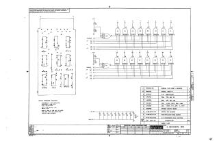
This document is a proprietary schematic diagram, copyrighted 1970 by Digital Equipment Corporation, intended for the test and maintenance of a digital circuit.
Key features of the document include:
- Circuit Function: The schematic details the design for "2 Decoders M151" (part number M151-0-1).
- Components: The circuit primarily utilizes nine DECI074H20 Integrated Circuits (ICs), along with various resistors (330 Ohm and 750 Ohm) and capacitors (0.01uF disc and 150uF tantalum). These components are listed in a "PARTS LIST."
- Power and Ground: All ICs operate with Pin 14 connected to +5V and Pin 7 connected to Ground.
- Inputs and Outputs: The circuit has "ENABLE" inputs (D2, V2) and numerous other labeled input/output lines feeding into and out of the decoding logic gates (E1-E8). An E9 IC appears to handle enable logic.
- General Specifications: Unless otherwise indicated, capacitors are 0.1uF, 100V, 20%, and resistors are 1/4W, 10%.
- Design Notes: Pins F2 and U1 are specifically designated for backplane twisted pair grounds and cannot be used by the circuit itself.
- Physical Assembly: The design includes an etched circuit board, eyelets, and a "Flip Chip - Magenta" handle.
- Creation Details: The schematic was drawn by Nancy Moore on November 23, 1970.
Site structure and layout ©2025 Majenko Technologies