M130
Order Number: XX-CA6F1-9D
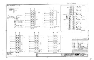
This document is a schematic diagram for the "PARITY CHECKERS AND GATES M130" module (part number M130-0-1), produced by Digital Corporation. Its primary purpose, as stated, is for test and maintenance.
The schematic details:
- Power Supply and Filtering: It shows the derivation and filtering of various voltage rails (+3.5V, 0.8V, and +3V) from an initial +5V input, utilizing resistor-capacitor networks and diodes (D662, D664).
- Even Parity Checkers: The core logic involves five distinct "EVEN PARITY" blocks (E1 through E5). Each block processes multiple input signals, which are routed through diode pairs connected to the 0.8V and +3V lines. Outputs from these parity blocks are also processed by associated XOR gates (also labeled E1-E5).
- Logic Gates Array: A substantial portion of the schematic illustrates a dense, interconnected array of logic gates and numerous diodes (labeled Dxx), suggesting a complex switching or processing network that likely interacts with the parity checkers.
- Component Specifications: General notes specify that unmarked capacitors are 0.01uF, 100V, 20%; all diodes are D664 unless otherwise noted; and the Integrated Circuits (ICs) used are DEC D4008P, with Pin 7 as Ground and Pin 14 as +5V.
- Parts List: A comprehensive Bill of Materials is provided, listing resistors (750Ω, 330Ω, 220Ω), various diodes (D662, D664) and capacitors (.01uF, 39uF), the DEC D4008P IC, along with mechanical components such as a handle, eyelets, and the etched circuit board.
Site structure and layout ©2025 Majenko Technologies