G737
Order Number: XX-21646-F0
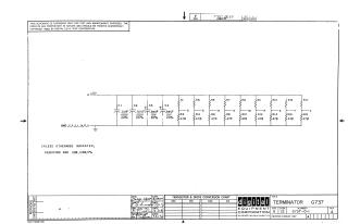
This document is a proprietary schematic diagram titled "TERMINATOR G737," part number G6737-0-1, Revision A, copyrighted in 1970 by Digital Equipment Corporation. It is provided for test and maintenance purposes only.
The schematic details a circuit operating from a +5V supply. This supply is decoupled by four capacitors (C1, C2 at 0.01uF/100V; C3, C4 at 0.39uF/10V, all 20% tolerance) connected to a common ground labeled GND C, F, J, L, N, R, U.
The circuit features nine termination networks, each composed of two 470-ohm resistors (e.g., R1/R2, R3/R4, up to R17/R18) connected in series between the +5V rail and ground, with intermediate tap points labeled D, E, H, K, M, P, S, T, and V. A general note states that unless otherwise indicated, resistors are 220 ohms, 1/4W, 5%. The drawing was drafted by George Wyatt on 8/24/70.
Site structure and layout ©2025 Majenko Technologies