G715
Order Number: XX-7318F-B6
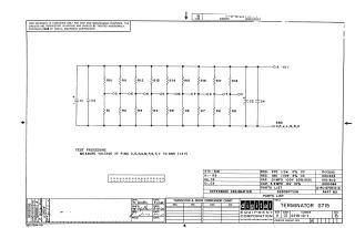
This document is a schematic diagram for a proprietary "TERMINATOR G715" circuit, copyrighted by Digital Equipment Corporation in 1968, and intended solely for test and maintenance purposes.
The circuit features a network of resistors (R1-R18) and capacitors (C1-C4) designed to operate with a +10V input and common ground. It provides multiple output pins (D, E, H, K, M, P, S, T, V) at specific points within the resistor network.
A test procedure is included, instructing measurement of the voltage at these output pins relative to ground, with an expected value of +4V, suggesting its function as a voltage divider or termination network.
The parts list details the components, including 270 Ohm and 180 Ohm resistors, and 0.01 MFD and 3.9 MFD capacitors with their respective specifications.
The document itself is identified as G715-0-1, Revision B, and was drawn and checked in August-September 1968.
Site structure and layout ©2025 Majenko Technologies