G705
Order Number: XX-13851-49
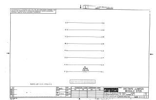
This document is a schematic diagram for the DECTAPE JUMPER MODULE G705 from Digital Equipment Corporation, with the module number G705-0-1, Revision A.
The schematic primarily illustrates a series of connections between various labeled points (e.g., C to D, E to H, J to K, etc.). One notable component shown is a resistor, R1 (15,000 Ohms, 1/4 Watt, 5%), which is part of the F to L connection.
According to the top left notice, the schematic is proprietary to Digital Equipment Corporation, copyrighted in 1967, and is furnished solely for test and maintenance purposes. The document also includes a reference to a Parts List (A-PL-G705-0-0) and a Transistor & Diode Conversion Chart, and indicates drawing dates in October 1967.
Site structure and layout ©2025 Majenko Technologies