G7006
Order Number: XX-C4EC4-0B
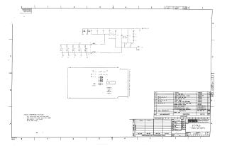
This document is an engineering drawing for a Digital Equipment Corporation I/O Bus Terminator #4, dated April 21, 1972 (Revision C).
It presents an electrical schematic detailing the circuit design for terminating an I/O bus, featuring various diodes, resistors, and capacitors. A significant component in the circuit is identified as an I.C. DEC 2501 (labeled as E1). The schematic indicates several voltage levels, including -0.7V, -2.2V, and -15V.
General specifications are provided for components, such as all resistors being 1.5K (5% 1/4W) or 100 ohm (5% 1/4W), all capacitors being 0.01uF (20% 100V) or 3.9uF (10% 10V TANT), and all diodes being D662.
The document also includes a comprehensive parts list (Bill of Materials) detailing component quantities, reference designators, descriptions, and part numbers for items like the IC, resistors, capacitors, diodes, an etched circuit board, an eyelet, and a flip-chip handle. Additionally, it references associated documentation for module ECO history, assembly/drilling layouts, and X-Y coordinate hole locations.
Site structure and layout ©2025 Majenko Technologies