G590
Order Number: XX-1908F-A7
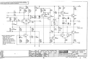
This document is a schematic diagram for a Filtered Differential Amplifier, model G590, copyrighted by Digital Equipment Corporation in 1969. It is furnished solely for test and maintenance purposes and its circuits are proprietary.
The schematic details the circuit connections, including various inputs (L, M, S(-IN), K, P(+IN), R) and outputs (V(OUT), F(ANALOG GND), D(+15V), E(-15V)).
General component specifications are provided: capacitors are typically 100V, diodes D664, resistors 1/4W 5%, and transistors DEC 2219, unless otherwise marked on the diagram. Specific installation instructions include installing heat sinks around transistors Q3 and Q4 (part number DEC1209619) and using etch board A 207E.
A "Transistor & Diode Conversion Chart" lists corresponding EIA and DEC part numbers for various components used in the circuit, such as D662 (IN645), D664 (IN3606), DEC6534D (MPS6534D), 2N4250, DEC2219 (2N2219), and SDA-5.
The document also contains administrative details including revision history, drawing (1968), checking (1969), engineering (1969), and production (1974) dates, as well as the document number CS G590-0-1, Revision E.
Site structure and layout ©2025 Majenko Technologies