G022
Order Number: XX-92193-57
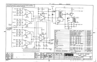
This document is a schematic diagram for a "FOUR INPUT SENSE AMP. GO22" circuit, designed and copyrighted in 1967 by Digital Equipment Corporation. It is stated to be proprietary and intended solely for test and maintenance purposes.
The schematic illustrates a circuit capable of processing signals from four distinct inputs (FIELD 0 through 3), typically connected via a 9-pin ITT Cannon connector. These inputs are conditioned through RC networks and then fed into multiple integrated circuits (MC1541L). The design includes a power management section with transformers (T1, T2), transistors (Q1, Q2), and diodes, which generates various operating voltages such as +10V, -15V, and -5.5V from an initial +5.5V input. Additional controls like "STROBE" and "SLICE LEVEL (-4.5V)" are also indicated.
Accompanying the schematic are a comprehensive parts list, detailing components like capacitors, integrated circuits, transformers, transistors, resistors, and diodes with their descriptions and part numbers. There is also a "Transistor & Diode Conversion Chart" cross-referencing DEC part numbers with EIA equivalents. The document includes revision history and creation details, showing it was drawn by M. Haller, checked by R. Silverman, and engineered by D.J. Chin in July 1967.
Site structure and layout ©2025 Majenko Technologies