G008
Order Number: XX-14309-D6
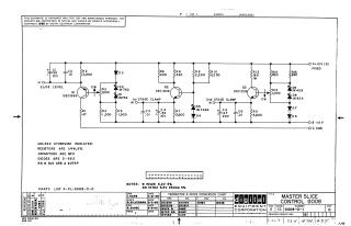
This document is a proprietary schematic diagram for the "Master Slice Control G008" circuit, copyrighted in 1965 by Digital Equipment Corporation (DEC) and intended for test and maintenance purposes.
The schematic illustrates a circuit with an input labeled "SLICE LEVEL" and output connections for "1st STAGE CLAMP" and "2nd STAGE CLAMP," operating with fixed power supplies of +10V, -15V, and ground. It features three transistors (Q1 DEC999, Q2 DEC2219, Q3 DEC2219), numerous resistors (R1-R15), capacitors (C1-C6), and diodes (D1-D9).
General specifications indicate that resistors are 1/4W, 5%; capacitors are in microfarads (MFD); and diodes are typically D-662, with specific notes for IN429 (6.2V, 5%) and IN762 (5.5V, 250mW, 5%). Resistors R3 and R13 have a special part number (#275P).
A "Transistor & Diode Conversion Chart" provides equivalences between Digital Equipment Corporation (DEC) and EIA part numbers, such as DEC999 (MM999), DEC2219 (2N2219), and D662 (IN645), noting that IN429, IN762, and IN748A numbers are consistent across both standards.
The document references a separate parts list (A-PL-6008-0-0) and includes revision history, with drawing and checking dates in April-May 1965. The drawing number is G008-0-1, Revision D.
Site structure and layout ©2025 Majenko Technologies