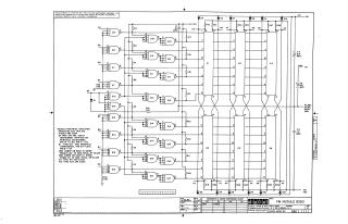
FM MODULE B250
Order Number: B250-0-1
This document presents a proprietary schematic diagram for the FM Module B250, copyrighted by Digital Equipment Corporation in 1967 for test and maintenance purposes. The circuit primarily features a series of logic gates, with E7 through E19 identified as Texas Instrument SN7440N or Fairchild U6A900959X, and E1 through E6 as Fairchild U6A903059X. Power supply specifications indicate +1.8V on Pin 14 and -3V on Pin 7 for E7-E19, and +1.8V on Pin 12 and -3V on Pin 5 for E1-E6.
The schematic includes various resistors (R2-R29 with values of 6,800 or 3,900 ohms, and R30-R32), diodes (D1-D13, specified as D664, convertible to IN3606), and capacitors (C1-C4). Notes specify component details: resistors are 1/4W, 5%; diodes are D664. Decoupling capacitors of 0.1 MFD are required for each IC, connecting from +1.8V to GND and from -3V to GND, totaling 19 capacitors for each supply rail. The circuit operates with multiple voltage rails including +10V, +1.8V, -3V, and -15V, along with a ground connection.
Site structure and layout ©2025 Majenko Technologies