ADDER GATE B167
Order Number: B167-0-1
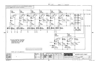
This document presents an electronic schematic diagram for an "ADDER GATE B167" circuit, copyrighted in 1966 by Digital Equipment Corporation and intended for test and maintenance purposes. The circuit comprises multiple stages of transistor-diode logic, utilizing transistors (Q1-Q8), various diodes (primarily D664 and D662), numerous resistors, and two capacitors (C1, C2). It operates with power inputs of +10V, -15V, and a ground connection. Inputs are labeled with letters from N to U, and outputs are designated as 'O D'. General component specifications are provided, indicating that transistors are 2N4258, resistors are 1/4W 5%, and diodes are D662, unless otherwise specified. A conversion chart for transistors and diodes is included. The document also references a parts list (A-PL-B167-0-0) and lists revision history.
Site structure and layout ©2025 Majenko Technologies