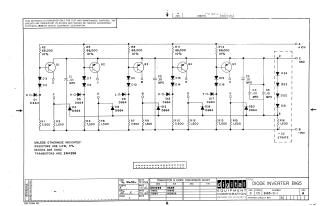
DIODE INVERTER BI65
Order Number: B165-0-1
This document is a schematic diagram for a Diode Inverter circuit, identified as BI65. It specifies that the schematic is for test and maintenance purposes only, and the circuits are proprietary, copyrighted by Digital Equipment Corporation in 1966.
The circuit features five transistor stages (Q1-Q5), each with associated input diodes, output diodes, and resistors. Common resistors (R2, R5, R8, R11, R14) are connected to a +10V supply, while other resistors (R1, R3, R4, R6, R7, R9, R10, R12, R13, R15) are connected to a -15V supply. Capacitors (C1-C5) are integrated throughout the circuit. A string of diodes (D21-D24) and a resistor (R16) connect to a -3V "STRATE" line.
General component specifications are provided: resistors are 1/4W, 5% (unless otherwise indicated), diodes are D662 (though many specific diodes in the circuit are D664), and transistors are 2N4258. A conversion chart lists EIA equivalents for DEC components: 2N4258 (DEC) is the same as EIA, D662 (DEC) is 1N645 (EIA), and D664 (DEC) is 1N3606 (EIA). The drawing date is October 18, 1966.
Site structure and layout ©2025 Majenko Technologies