M220b
Order Number: XX-XXXXX-XX
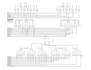
This document is a technical schematic diagram for the M220B circuit. It illustrates a complex array of logic gates (7440, 7460, and 7474 series) and signal pathways. The diagram details the interconnections between various computer registers and control signals, including:
- Input/Control Signals: Includes various enables (AC, MQ, SR, SC, Data, IO, MA, PC, MEM, and Data Address) and shift/adder control lines (AND, Shift Right/Left, and Adders 0–5).
- Clock Signals: Distributes global clock signals (Bit 2/3, AC, MB, PC, MA, and Maclock) across the register banks.
- Logical Organization: The schematic is structured around registers (represented by 7474 D-type flip-flops) and combinatorial logic blocks that process inputs and manage data flow through the system.
- Annotation: The schematic notes that it is "Drawing Revision 1 (incomplete)" and was created by Robert Krten.
Site structure and layout ©2025 Majenko Technologies