Memory Extension Control
Order Number: XX-XXXXX-XX
This document consists of five schematic sheets detailing the memory extension control circuitry for the MC8I system.
- Sheet 1: Illustrates the memory extension control logic, including address decoding, manual preset functions, and interface controls for managing memory bank selection.
- Sheet 2: Focuses on the status and enable logic, detailing the handling of memory extension signals, interrupt inhibits, and processor control lines related to memory expansion.
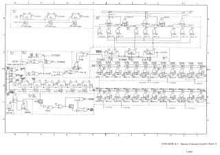
- Sheet 3: Displays the inhibit driver circuitry, which handles signal assertion for memory parity and the selection of specific memory banks (B-fields).
- Sheet 4: Details the X-axis selection matrix, showing the diode-based decoding logic used to select specific lines within the memory array based on address inputs.
- Sheet 5: Details the Y-axis selection matrix, providing the corresponding decoding logic for the Y-axis, which functions similarly to the X-axis to complete the memory address selection path.
The documentation follows DEC Standard 054 for signal naming conventions, where signals represent the asserted state for high (H) levels.
Site structure and layout ©2025 Majenko Technologies