Dep, Exam, Cont, Clear, Sing Step, Halt Switch, and Display Logic
Order Number: XX-XXXXX-XX
This document details the hardware logic and circuit design for various computer control keys and the system display.
Key Features:
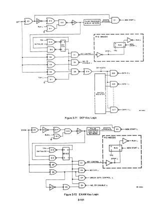
- Control Keys: It describes the logic for the "DEP" (Deposit), "EXAM" (Examine), "CONT" (Continue), and "CLEAR" keys, as well as the "SING STEP" (Single Step) and "HALT" switches. These circuits interface with the timing generator (part of the M8330 module) to initiate specific operations like memory starts or clearing registers.
Display Logic: The document explains how the front panel indicator lamps function.
- RUN Indicator: Controlled by the timing generator, this lamp switches between dim and bright states depending on whether timing cycles are being generated, helping to prolong bulb life.
- Data/Register Displays: A "Function Selector Switch" allows the operator to select which information (MD, AC, MQ, STATUS, or BUS) is displayed on the front panel. Logic gates (including NAND and NOR configurations) enable specific lamps based on the register content and the selected enable signal (MD, STATE, or DATA ENABLE).
Circuit Mechanics: The document provides detailed technical explanations of RC time constants and transistor switching to ensure indicator lights remain visible, as well as the specific logic used to interface bus data with front-panel display LEDs.
Site structure and layout ©2025 Majenko Technologies