Stack Schematic 8K X 12 Bit
Order Number: G234
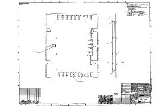
This document contains a set of technical schematics and parts lists for an 8K x 12-bit memory stack assembly. The documentation includes:
- Mechanical Layout and Assembly: Detailed diagrams showing the component side (Side 2) of the module, including the placement of integrated circuits (E1–E24) and associated board components.
- Schematic Diagrams: Detailed circuit logic for the memory stack, showing signal paths, transformations, and connections for address, inhibit, write, and return signals.
- Component Substitution List: A table identifying original parts and their acceptable substitutes for maintenance and repair.
- Technical Notes: Specifications regarding component lead length, memory system configurations (H212, G11/G15, G233/G234), and specific handling instructions for grommets and wiring.
- Parts List: A comprehensive inventory of electronic components used on the board, including resistors, diodes, capacitors, and transistors, with their respective specifications and part numbers.
Site structure and layout ©2025 Majenko Technologies