Engineering Drawings
Order Number: XX-XXXXX-XX
Summary This document, Chapter 10 of a technical manual, provides a guide to interpreting DEC engineering drawings and the standardized symbols used within them. Key sections include:
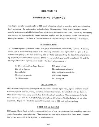
- Drawing Numbering: Explains the system for identifying drawings, which uses a five-part code to specify drawing type (e.g., schematic, wiring diagram), size, equipment number, and series.
- Circuit and Logic Symbols: Provides a detailed visual reference for standard DEC symbols, including transistors, gates, pulse inverters, amplifiers, flip-flops, and delay modules.
- Logic Levels and Pulse Standards: Defines the electrical standards for DEC equipment, including logic level voltage ranges (ground to -3V), pulse amplitudes, durations (40, 70, or 400 nsec), and transition behaviors.
- Semiconductor Substitution: Includes a reference table (Table 10-1) for substituting standard EIA components for DEC-specific semiconductors used in PDP-8 modules.
Site structure and layout ©2025 Majenko Technologies