Power Control 854
Order Number: Z854
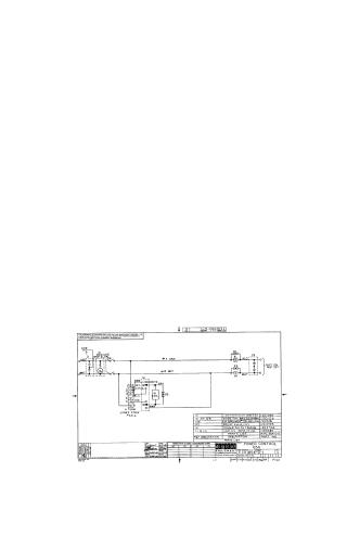
This document is a technical schematic for a Digital Equipment Corporation power control circuit (Model 854), dated 1968. The diagram illustrates the wiring and electrical components used to manage a "Fast On/Fast Off" power interface.
Key features include:
- Components: The circuit utilizes a light (Omni Glow), a circuit breaker, a relay (EM-4), a toggle switch, capacitors, and diodes (GRS20SP4B4).
- Connectivity: It includes a 6-terminal Jones strip for external connections and specifies wire color coding (#14 Orange and #14 White).
- Purpose: The document is explicitly marked for test and maintenance purposes.
- Parts List: A detailed table correlates reference designators (I1, D1-D3, CB1, K1, S1, C1-C2) with their specific part numbers for maintenance and replacement.
Site structure and layout ©2025 Majenko Technologies