One Step Power Control Panel 834
Order Number: Z834
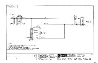
This document is an electrical schematic for the "One Step Power Control Panel 834," designed by Digital Equipment Corporation in 1964. The diagram illustrates the wiring connections for the power circuit, including:
- Key Components: The circuit utilizes two capacitors (C1, C2), an "Omni Glow" indicator light (I1), a circuit breaker (CB1), a six-terminal Jones strip (connection point), and a toggle switch (S1) that controls a relay coil (K1).
- Functional Layout: The power input flows through the circuit breaker and indicator light. The toggle switch determines the operational mode (Remote/Local), which in turn energizes the K1 relay coil to control the output.
- Specifications: The notes section details specific parts used, such as Cornell Dublier 2.0uF 600VDC capacitors, a 115VAC relay, a 20-amp circuit breaker, and General Electric thyristors (D1, D2, D3).
Site structure and layout ©2025 Majenko Technologies