Power Monitor
Order Number: W506
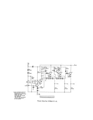
Summary This document provides a technical schematic for a "Power Monitor" circuit. The design utilizes a series of transistors (DEC 2219A), diodes (D664), and capacitors (6.8 MFD, 35V tantalum) to monitor voltage levels. The circuit includes several output terminals (J, K, L, M) and inputs for +10V and -15V. It also specifies general component tolerances, noting that resistors are 1/4W with 10% tolerance unless otherwise indicated, and defines the specific hardware types used for the tabs and potentiometer (R1).
Site structure and layout ©2025 Majenko Technologies