Teletype Connector W078
Order Number: W078
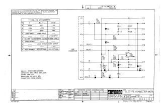
This document is an electrical schematic for a Digital Equipment Corporation Teletype Connector (W078), dated 1969. It details the circuitry required to interface with a teletype, including an amplifier connector section.
Key technical information included:
- Pin Assignments: A table providing voltage and signal logic requirements for pins A, B, C, H, U, M, D, E, K, and V across different model configurations (8, 8I, 8L, and DCO8).
- Component Specifications: A schematic diagram illustrating the arrangement of resistors, capacitors, diodes (D671), and a transistor (DEC 6534D) within the unit.
- Standard Defaults: Unless otherwise noted, capacitors are 0.01μF 100V (20%), resistors are 1/4W (5%), and the connector is DEC# 1209456.
- Reference Data: It includes a transistor and diode conversion chart and notes that the schematic is intended for test and maintenance purposes only.
Site structure and layout ©2025 Majenko Technologies