Cable Connector M957
Order Number: M957
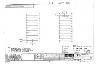
This document is an engineering schematic for the Digital Equipment Corporation M957 cable connector. It displays a pinout diagram for connectors labeled A1 through V2 and provides a table detailing component variations (M957, M957-YA, and M957-YB). The schematic specifies how resistors (R1 through R4) and diodes (D2 through D4) are integrated, with notes indicating that dotted lines denote the "YA" version of the component, while marked "X" lines indicate elements specific to the "YB" version.
Site structure and layout ©2025 Majenko Technologies