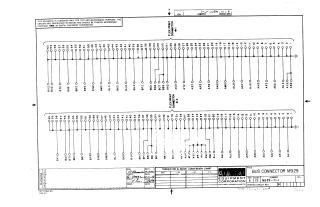
Bus Connector M929
Order Number: M929
This document is a technical schematic for the M929 Bus Connector, produced by the Digital Equipment Corporation in 1969. The diagram illustrates the pinout and electrical routing for two flex print connectors. It maps out sixty signal points for each connector, showing how specific bus signals (labeled with alphanumeric identifiers like BVI0 through AB2O) are interconnected and terminated, providing a clear layout of the circuit's connectivity for testing and maintenance purposes.
Site structure and layout ©2025 Majenko Technologies