Reader/Punch Control
Order Number: E253
This document serves as the technical documentation and schematic set for the Reader/Punch Control circuit board manufactured by the Digital Equipment Corporation.
The document is divided into three primary sections:
- Page 1: Provides the physical component layout (PCB assembly), identifying the placement of various integrated circuits (E1 through E44), resistors, capacitors, and connectors, accompanied by a comprehensive bill of materials (parts list) detailing specific electronic components used.
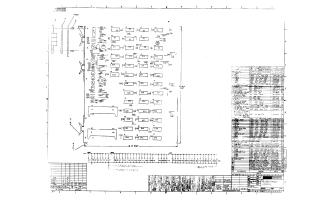
- Page 2: Contains the primary logic schematic for the control unit, detailing the signal flow for the punch feed, motor control, and various strobe and synchronization signals required to operate the hardware interface.
- Page 3: Details the input/output logic and buffer circuitry, specifically illustrating the "Punch Buffer" and "Reader Buffer" configurations using 8271 chips and associated gate logic to process data bits 0 through 7.
Overall, these schematics provide the necessary engineering details to maintain, troubleshoot, or replicate the logic and assembly of the reader/punch control interface.
Site structure and layout ©2025 Majenko Technologies