Bus Loads
Order Number: M8320-0-1
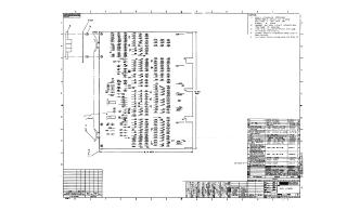
Summary This document provides the technical schematics and component assembly details for a "Bus Loads" electronic circuit board (Digital Equipment Corporation).
- Assembly Drawing: The first page provides a physical layout of the circuit board, identifying the placement of numerous resistors (R) and diodes (D) and referencing their corresponding parts list.
- Schematic Diagram: The second page details the electrical circuitry, showing how the various resistors and diodes are interconnected to manage bus load signals. It includes power supply connections, voltage regulation points (+5V, -15V), and numerous signal lines (e.g., DATA, MEM START, INT, BUS RUN).
- Parts List: The right-hand margin contains a parts list specifying components such as transistors (2N3725), diodes (D664), capacitors (various values), and resistors, along with their respective manufacturing part numbers and physical layout specifications.
Site structure and layout ©2025 Majenko Technologies