Interrupt Control M7821
Order Number: M7821-0-1
This document provides the engineering schematics and parts reference for the M7821 Interrupt Control module, manufactured by Digital Equipment Corporation.
Key details include:
- Schematic Diagram: A detailed logic gate diagram illustrating how the module processes bus requests, interrupt handling, and bus grant signals.
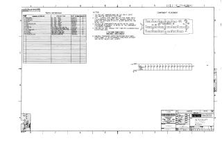
- Parts Reference: A list of integrated circuits (ICs), resistors, and capacitors required for the assembly, including specific DEC part numbers.
- Component Placement: A layout guide showing the physical positioning of the ICs (E1–E17) on the module board.
- Technical Specifications: Notes regarding jumper configurations for vector bits, specific power requirements (pin 7 for GND and pin 14 for +5V), and general component standards for resistances and capacitance.
Site structure and layout ©2025 Majenko Technologies