Clock Counter M709
Order Number: M709
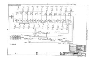
This document is a technical schematic for a "Clock Counter M709," designed by the Digital Equipment Corporation in 1968. The circuit uses various integrated circuits (ICs) to manage clock inputs and counting functions. It features input lines for I/O buses (0–11), overflow logic, and a series of clocked counter stages. The diagram includes logic gates (E7, E9, E11, E22) to handle timing and control signals, such as load, gate, and clear functions. Additionally, the document includes a parts list identifying specific IC types, resistors, diodes, and capacitors used to construct the circuit, along with pin-out configuration notes (Pin 7 for GND and Pin 14 for +5V).
Site structure and layout ©2025 Majenko Technologies