Reader Control
Order Number: M7050-0-1
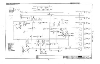
This document is a technical schematic for a "Reader Control" circuit board (part number M7050-0-1) designed by Digital Equipment Corporation.
The schematic details the logic and signal routing required to interface with external devices (such as a paper tape reader). Key components and features include:
- Logic Gates and Integrated Circuits: The circuit utilizes various standard logic gates (represented by E1 through E19) to process signals such as "Stop Complete," "Run Flag," "Shift," and "Initialize."
- I/O Bus Interface: The circuitry manages the flow of information between the device and the system I/O bus (designated as I/O BUS IN 1 through IN 10).
- Control Signals: It includes specific control logic for "On/Off Line" status, "Stop Delay," and "Inhibit Strobe."
- Power and Support Components: The diagram includes power distribution rails (+5V and +3V), various resistors, capacitors, and a transistor/diode conversion chart to facilitate maintenance and testing.
- Operational Notes: The document specifies that it is for test and maintenance purposes and lists the specific IC types used throughout the design, such as DEC 74xx series logic.
Site structure and layout ©2025 Majenko Technologies