Tapped Delay Line M321
Order Number: M321
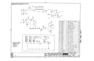
This document is a technical schematic for a Digital Equipment Corporation "Tapped Delay Line M321" circuit board. The schematic details the electrical configuration of a 25NS delay line circuit, including the integration of transistors (DEC 4258 and DEC 3009B), various resistors, capacitors, and diodes (FD777 and D662).
The document also provides:
- A comprehensive parts list (bill of materials) including 26 individual items, their corresponding DEC part numbers, descriptions, and quantities.
- A transistor and diode conversion chart for cross-referencing DEC components with EIA standards.
- A mechanical and assembly reference, including notes on hole layout and coordinate location.
- General design specifications, noting that capacitors are 0.01uF, 100V, 20%; resistors are 1/4W, 5%; and transistors are DEC 4258.
Site structure and layout ©2025 Majenko Technologies