Main Register M221
Order Number: M221
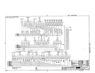
This document is a technical schematic for the "Main Register M221," a digital circuit component manufactured by Digital Equipment Corporation in 1967.
The schematic details the logic flow and electrical connections for the register, which includes various integrated circuits (ICs), transistors, and diodes. Key features include:
- Logic Gates: The circuit utilizes multiple logic gates (E1–E21) to process various signals, including "Partial Sum," "Output," and "Address Match" signals.
- Input/Output Signals: It highlights numerous control signals such as "Load AC," "Load MB," and various "Enable" signals for register operations (e.g., Enable MQ, Enable PC, Enable RSW).
- Bus Connectivity: The schematic illustrates connections to "Reg Bus 2" and "Reg Bus 3," as well as "Adder" inputs and outputs.
- Component Details: A reference section identifies the integrated circuits used (such as the DEC 74H00N and 7474N) and provides a conversion chart for transistors and diodes.
- Power Requirements: The notes specify power distribution, noting that most ICs operate on +5V (pin 14) with grounds at pin 7, with specific exceptions noted for IC E5.
Site structure and layout ©2025 Majenko Technologies