8 Wide And-Nor M17c
Order Number: M170
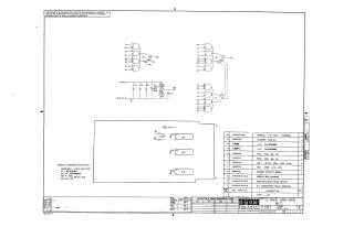
This document is a technical schematic diagram and parts list for a Digital Equipment Corporation circuit board, specifically an M17C "8 Wide AND-NOR" gate module, dated 1970.
Summary:
- Schematic Design: The diagram illustrates the wiring for several logic gates, including the interconnections for inputs (V1-T2, M1-H2) and outputs. It includes a power supply section involving +5V connections and capacitor/resistor networks.
- Component Specifications: The document specifies that capacitors are generally 0.01µF, 100V, 20%, and identifies the Integrated Circuits (ICs) used as DEC1074H62 and DEC1074H53.
- Parts List: The accompanying table lists the necessary components to build the board, including resistors, capacitors, eyelets, a handle, and the printed circuit board itself. It also references auxiliary documentation, such as the assembly/drilling hole layout and X-Y coordinate locations.
Site structure and layout ©2025 Majenko Technologies