2 Decoders MI52
Order Number: M152
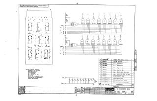
This document is a technical schematic for the "2 Decoders MI52" circuit board (part number MI52-0-1) produced by the Digital Equipment Corporation in 1970.
Key features of the schematic include:
- Circuit Design: The board consists of two sets of logic decoders utilizing eight integrated circuits (E1 through E8) to handle binary inputs (2^0, 2^1, 2^2) and enable signals.
- Component Specifications: The document includes a detailed parts list featuring resistors, capacitors, and IC chips (DEC1074H21 and DEC1074H20).
- Board Layout: It provides a physical layout reference for the placement of components on the circuit board.
- Technical Constraints: The schematic notes that capacitors are .01uF (100V, 20%) and resistors are 1/4W (10%). It specifies power requirements (Pin 7 for Ground, Pin 14 for +5V) and prohibits the use of pins F2 and U1, as they are reserved for backplane twisted pair grounds.
Site structure and layout ©2025 Majenko Technologies