Seven 3 Input Nand Gates MI45
Order Number: M145
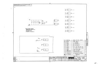
This document is a technical schematic diagram for a "Seven 3 Input NAND Gates" printed circuit board (model MI45) produced by Digital Equipment Corporation in 1970.
The schematic illustrates the electronic circuit design, featuring:
- Logic Gates: Connections for seven 3-input NAND gates (using DEC1074H10 ICs).
- Power and Passive Components: A power distribution circuit for the +5V supply, including a 39uF tantalum capacitor, a 220-ohm resistor, and a 330-ohm resistor.
- Notes: Standard specifications for the board, noting that resistors are 1/4W, 5% and standard capacitors are 0.01uF, 100V, 20%.
- Parts List: A comprehensive table listing the required components, including the etched circuit board, ICs, resistors, capacitors, and assembly hardware (eyelets and handles).
Site structure and layout ©2025 Majenko Technologies