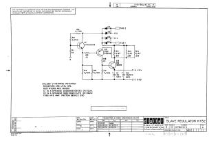
Slave Regulator K732
Order Number: K732
This document is a technical schematic diagram for a Slave Regulator circuit, designed by Digital Equipment Corporation in 1967. The schematic details the electronic components of the circuit, which include three transistors (Q1: DEC2219A, Q2: DEC6534D, and Q3: 2N3055), several resistors, four rectifiers (D1-D4), and two capacitors (C1 and C2). The circuit is designed to provide a +10V output. The document also includes a "Transistor & Diode Conversion Chart" to cross-reference Digital Equipment Corporation proprietary component numbers with industry-standard EIA numbers.
Site structure and layout ©2025 Majenko Technologies