Calibrated Timer Control K374
Order Number: K374
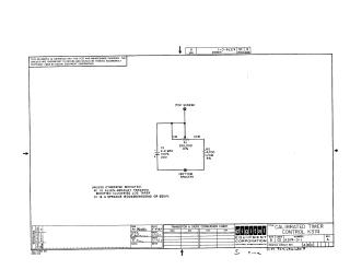
Summary: This document is a technical schematic diagram for a Calibrated Timer Control (K374), copyrighted in 1967 by the Digital Equipment Corporation. The circuit consists of a 250,000-ohm potentiometer (R1), a 4,700-ohm resistor (R2), and a 2.2 MFD 20V capacitor (C1). The schematic specifies component requirements, noting that R1 should be an Allen-Bradley TSRA2541 modified clockwise log taper, and C1 should be a Sprague 150D225X9020A2 or equivalent. The document is intended for test and maintenance purposes.
Site structure and layout ©2025 Majenko Technologies