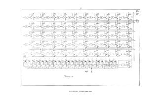
Pdp-8/L Control Panel
Order Number: G921
This document is a technical schematic diagram for the PDP-8/L Control Panel. It illustrates the logic circuitry and interconnected components used to manage the computer's operational states. The schematic includes a series of integrated circuits (ICs) arranged in rows, representing various registers and control functions such as "Data Field," "Instruction Field," "Load Address," "Deposit," "Examine," and "Single Step." It also details the input/output pin configurations, power supply connections (+5V, -15V, and Ground), and the specific logic gate architecture required to facilitate the control panel interface of the PDP-8/L system.
Site structure and layout ©2025 Majenko Technologies