Power Sequence Delays and Decoder G827
Order Number: G827
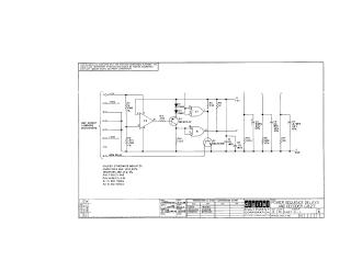
This document provides the technical schematic and component layout for the G827 Power Sequence Delays and Decoder module, manufactured by the Digital Equipment Corporation in 1969.
The schematic illustrates an electronic circuit involving operational amplifiers (MC1709CG), logic gates (7401N), transistors, and various resistors and capacitors. It includes power inputs for +11V, +30V, and +5V, as well as connections for a "Lock" signal and a "Memory Relay." A transistor and diode conversion chart is included to cross-reference Digital Equipment Corporation proprietary part numbers with standard industry components (e.g., DEC6534/MPS6534, DEC3009C/2N3009, and D664/IN3606). The second page provides a physical layout map of the components on the printed circuit board to assist with maintenance and identification.
Site structure and layout ©2025 Majenko Technologies