24V Regulator Control
Order Number: XX-XXXXX-XX
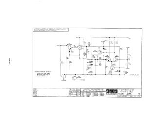
This document contains technical documentation for a -24V power supply regulator circuit manufactured by Digital Equipment Corporation in 1969.
- Schematic Diagram: The document provides a detailed electrical schematic for the G823 circuit, including a variety of transistors (Q1–Q7), diodes (D1–D6), resistors, and capacitors. It includes a conversion chart mapping DEC-specific component identifiers to standard EIA equivalents (e.g., DEC6534C to MPS6534).
- Component Layout: The second page provides a top-down physical layout diagram indicating the placement of all electronic components (resistors, capacitors, transistors, and diodes) on the circuit board, which is helpful for maintenance and identification purposes.
- Usage Notes: The document specifies that the circuit is proprietary and intended solely for test and maintenance. It also defines default values for unspecified components (capacitors are 0.01µF, resistors are 1/4W, 5%).
Site structure and layout ©2025 Majenko Technologies