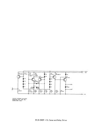
Rs-B-G809 -15v Sense and Relay Driver
Order Number: XX-XXXXX-XX
This document provides a schematic diagram for a -15V sense and relay driver circuit. The circuit utilizes several transistors (DEC2894-3 and DEC2904) and a network of diodes and resistors to monitor a voltage input and control outputs (E and F). It operates using dual power rails of +10V and -15V. Default component specifications for resistors (1/4W, 10%) and diodes (D-662) are noted for any components not explicitly labeled with specific values.
Site structure and layout ©2025 Majenko Technologies