Regulator Board 8A Core
Order Number: XX-XXXXX-XX
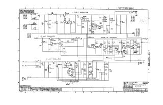
This document consists of a two-page schematic diagram for an 8A Core Regulator Board. The circuit design includes several power regulation and monitoring sections:
- Voltage Regulation: The board provides regulated outputs including a +5V regulator, a -5V regulator, and a +20V regulator (page 1), as well as a ±15V supply (page 2).
- Indicators and Monitoring: The design incorporates a "Power OK" indicator circuit and an "AC Low Indicator" circuit used for system status monitoring.
- Protection: The board features an overvoltage "crowbar" circuit to protect connected components.
- Configuration: The schematic includes detailed connectivity and component values, identifying various test points (TP) and terminal blocks (TB) for the power distribution rails. Page 2 also notes a configuration jumper (W3) to enable or disable the AC low output.
Site structure and layout ©2025 Majenko Technologies