Cable Terminator G795
Order Number: XX-XXXXX-XX
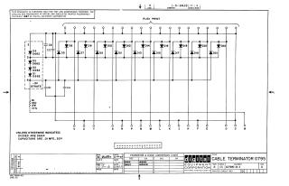
This document is a technical schematic for the Digital Equipment Corporation Cable Terminator G795 (dated 1967). The circuit diagram illustrates a flexible printed circuit layout used for signal termination. Key components include:
- Diodes: The circuit utilizes a series of diodes, specifically D662 (for pins 1–4) and D664 for the remaining positions (D5 through D22).
- Capacitors: The schematic includes capacitors C1 through C4, with a general specification of .01 MFD at 50V.
- Resistor: A 120-ohm, 2-watt, 10% resistor (R1) is incorporated into the terminal path.
- Connectivity: The board interfaces via multiple labeled pins (V, U, T, S, R, P, N, M, L, K, J, H, F, E, D, C, B) and a -3V source.
The document includes a conversion chart noting that D662 parts are equivalent to 1N645 diodes, and D664 parts are equivalent to 1N3606 diodes.
Site structure and layout ©2025 Majenko Technologies