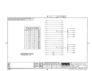
Cable Connector G783
Order Number: XX-XXXXX-XX
This document is a technical schematic from 1969 by the Digital Equipment Corporation detailing the wiring configuration for the G783 Cable Connector. The schematic outlines the pin-to-pin connections for pins 1 through 28, noting that pins 6, 7, 8, 14, 19, 20, 21, 22, 23, 24, 25, 26, 27, and 28 are interconnected. It also includes a "Color Coding Chart" based on standard Belden pair designations, which lists shield and wire colors for nine different pair sets. Additionally, the document specifies that resistors R1 and R2 (associated with pins 17 and 18) are 10-ohm, 1/4-watt, 10% tolerance components.
Site structure and layout ©2025 Majenko Technologies