Positive Logic Jumper Card G742
Order Number: XX-XXXXX-XX
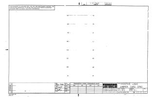
This document is a technical schematic for a Digital Equipment Corporation "Positive Logic Jumper Card" (G742), dated December 1970. The diagram displays a series of pin-to-pin connections (labeled D2 to C1, H2 to F1, K2 to J1, M2 to L1, P2 to N1, S2 to R1, R2 to U2, and U1 to V1) designed for test and maintenance purposes. The document notes that these circuits are proprietary.
Site structure and layout ©2025 Majenko Technologies