Bus Control G726
Order Number: XX-XXXXX-XX
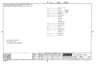
This document is a technical schematic diagram for a Bus Control circuit (G726), published by Digital Equipment Corporation in 1969. The schematic outlines the configuration of input/output pins (labeled C through V) and identifies a specific 56pF, 100V, 5% capacitor (C1) that is not used on the G726-YA variation. It specifies that all connection points indicated by a circle with a diagonal line are split lugs, and it includes a revision history block and a reference for a transistor and diode conversion chart. The document is intended for test and maintenance purposes only.
Site structure and layout ©2025 Majenko Technologies