Read Write Driver G223
Order Number: XX-XXXXX-XX
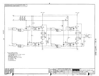
This document provides the technical engineering schematics and component layout for the Digital Equipment Corporation "Read Write Driver G223" module.
Summary of Contents:
- Schematic Diagram: Details the electrical circuitry of the driver, including the integration of SN74H00 integrated circuits (E1, E2, E3), transistors (Q1-Q4), transformers (T1-T5), and various capacitors, diodes, and resistors. It specifies power requirements (-24V and +5V) and identifies specific component models, such as the D664 diodes and the specific Sprague part numbers for the transformers.
- Component Layout: Provides a visual map of the physical board, showing the placement of all resistors, capacitors, transistors, diodes, transformers, and IC chips on the printed circuit board.
- Reference Data: Includes a transistor and diode conversion chart and revision history notes from 1969.
Site structure and layout ©2025 Majenko Technologies