I/O Bus Terminator #3
Order Number: XX-XXXXX-XX
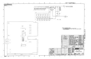
Summary: This document is a technical schematic for an "I/O Bus Terminator #3" circuit board, manufactured by Digital Equipment Corporation for the PDP-10 computer system.
The schematic details the electrical configuration of the board, which includes:
- Components: A resistor network (R1–R13), a capacitor bank (C1–C6), a diode array (D662), and a primary integrated circuit chip (E1, DEC 2501).
- Circuitry: The diagram illustrates the connectivity between these components, including power rails (-15V and -0.7V) and external bus connections (labeled AT through BS).
- Specifications: The notes specify that all resistors are 1.5K 5% 1/4W, and capacitors are .01µF 20% 100V ceramic discs, unless otherwise marked.
- Parts List: The document includes a tabular parts list identifying the specific components, quantities, and their associated DEC part numbers required to assemble the board.
Site structure and layout ©2025 Majenko Technologies